


Yet another moodlight based around WS2811 (neopixel) strip, and why not.
Actually this project satisfies a number of things I want to achieve (and lays the foundation for some others):
- It is an Ikea Hack. I always think that Ikea furniture (and especially lights) shout out for repurposing – and I’m not alone here: see www.ikeahackers.net/
- It’s a mood light – need I say any more?
- It’s a functional side light (still) but uses little energy (maybe around 4 watts).
- It’s based around an Amtel ATTiny85 microcontroller.
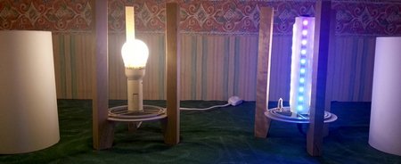
On the left, the original lamp, on the right, the hack moodlight.
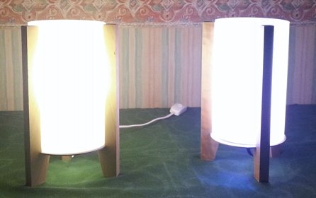
Comparison between original side light and hacked side light. In terms of illumination, there is little practical difference, although I could have put a brighter bulb in the original.
I am going to talk through the project over a few blog posts, not because it is a particluarly complex project, but there are a number of decisions that I have made as I have gone through the process of designing, building the hardware, and writing the software, and I always think it is instructive to learn from mistakes.
Part 1 – the initial idea and rough design
I bought some RGB LED strip – the stuff that allows you to set all the LEDs in the strip to the same colour by mixing the amount of red, green, and blue light – to play around with light boxes for the Tea House. This strip came with a cheap controller, and that gave me at least something to play with. First impression was how bright the light could be.
I built a box frame from MDF (painted white inside and black outside), stuck a translucent glass door (50p from Ikea – I picked up a few!), and stuck a few lengths of the strip to the box. Once I screwed the controller on the back, I had a reasonably useful box – although I found there wasn’t enough diffusion and could still see the LEDs.
What this needed was a better controller. Since I had an Arduino, I picked up an RGB shield and started to play with a bit of programming.
Unfortunately for me, I came across a very cool-looking design (http://blog.simtronyx.de/en/mood-lamp-with-a-digital-rgb-led-strip-ws2811-an-arduino-acrylic-glass-and-a-few-parts-from-the-hardware-store/) based on addressable RGB pixel strip (which I’ll refer to as WS2811 RGB strip). I thought I would build one – but when I looked at the price for Plexiglas (Perspex), I thought that I’d have a look for a cheaper alternative.
As it happens, I have a few Ikea lamps lying around that I picked up some time ago. (As far as I know, they are now discontinued, sadly). I though, “I could make a rainbow lamp” – all it needs is some RGB strip, a controller, and a power supply. Not surprisingly, there are a number of different designs for aurora lights and rainbow lights. But these designs had something lacking – a usable white light mode, so I could still use the lamp as a table lamp.
As it happens, you can get hold of (warm) white LED strip quite easily. I prefer warm white to the rather clinical cool white that you get from simply turning the RGB leds on full.
I picked up some other things from Ebay, including some WS2803 integrated circuits – these can drive six RGB LEDs (or 18 indidual LEDs) using a similar protocol to the WS2811. I also bought some ATTiny 85 microcontroller chips. These are 8-pin integrated circuits that are the smaller sibling to the ATMega microcontroller that the Arduino uses.
So here was the beginning of my idea:
- A strip of warm white LEDs that can be on, off, or possibly dimmed.
- A strip of addressable RGB LEDs that can be programmed to provide mood lighting.
There were a couple of practical issues though:
- The white LEDs require a 12 volt supply, but the Arduino and the RGB strip require a 5 volt supply.
- The Arduino is quite big, and somewhat overkill for the project.
- There needs to be a simple user interface to control the light.
Tackle one thing at a time
With any project, it is good to divide it up into chunks that you can build and test. For me this was the breakdown:
- Work out how to drive a strip of 10 RGB LEDs to create a rainbow and other effects.
- Work out how to drive a 12 V LED strip at different intensities from an Arduino.
- Decide how to mount the LEDs in the lamp.
- Find out how to program an ATTiny 85 microcontroller.
- Transfer the code from Arduino to ATTiny.
- Build hardware (electronics) to fit the lamp.
- Create a suitable user interface to make a usable lamp.
I found some Arduino sketches for driving the WS2811 RGB strip – the version I have needs +5v, 0v, and a data line that has quite a strict protocol and timing requirement. I connected the RGB strip to the Arduino, loaded up a sketch and it worked!
Well, almost.
The idea is that for each LED on the strip, you send three bytes of data: each byte representing a intensity (0-255) of an LED. Since each RGB LED has three colours (red, green, blue) you send a byte for each of the colours. The good news is that you can mix colours quite nicely – I prefer subtlety – and these blend to create a colour somewhere between black (all LEDs off – 0) or white (all LEDs on – 255).
The problem is that the LEDs are wired as GRB not RGB – so the colours were wrong. Easy fix in the code to specify the correct order.
After a bit of faffing about (that’s a technical term), I got a few sample programs working to display different things (rainbow effect, “dripping” water droplet, the Larson scanner (aka Knight Rider light), a Star Trek red alert.
One thing I noticed, is that if I ran the Arduino of an external power supply (rather than the USB), the power regulator became rather warm – too warm for comfort, but this was not a problem running from USB.